


403
Sorry!!
Error! We're sorry, but the page you were looking for doesn't exist.
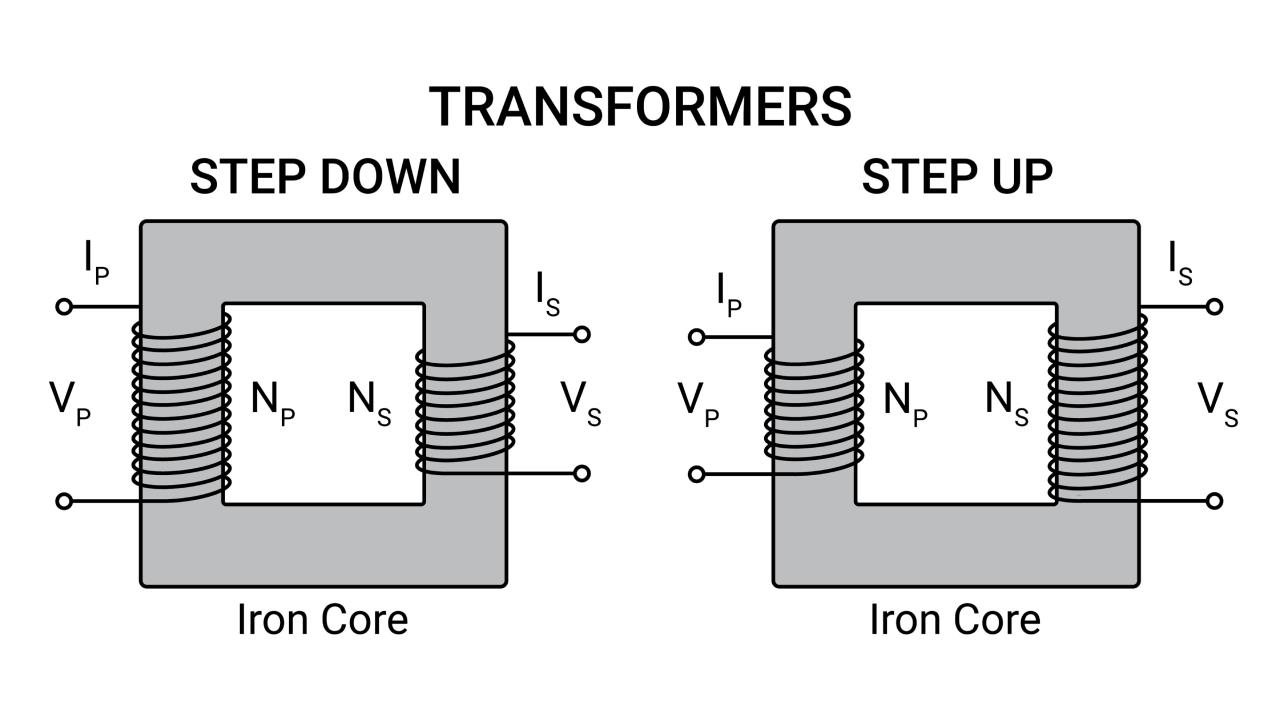
Step-Up Vs Step-Down Transformers: Definition And Key Differences
| Feature | Step-Up Transformer | Step-Down Transformer |
|---|---|---|
| Primary Function | Increases output voltage ($V_{out} > V_{in}$) | Decreases output voltage ($V_{out} < V_{in}$) |
| Turns Ratio | Secondary turns ($N_s > N_p$) | Primary turns ($N_p > N_s$) |
| Current | Output current is lower than input current | Output current is higher than input current |
| Primary Winding | Low-voltage side, uses thicker wire | High-voltage side, uses thinner wire |
| Secondary Winding | High-voltage side, uses thinner wire | Low-voltage side, uses thicker wire |
CNC ELECTRICS9-M Series Fully Sealed Oil-Immersed Transformer
Features a fully oil-filled, sealed corrugated tank that naturally adapts to oil expansion. Engineered for high efficiency and low loss to significantly save power consumption and operating costs.
-
Sealed corrugated tank for optimal heat dissipation
High mechanical strength & strong short-circuit resistance
Low no-load/load loss for maximum energy savings
Compact, reliable, and 100% maintenance-free
View Product Details
Beyond the Basics
Insulation Requirements
Choosing a transformer means looking at more than just the voltage ratio. The high-voltage side needs much stronger insulation to stop electrical arcing and prevent failure. In a step up transformer, that high-voltage side is the secondary winding. In a step down transformer, it is the primary winding.
Winding Location and Taps
Designers often place voltage-adjustment taps on the primary winding. Because of this, the primary winding is usually the outer coil so workers can reach it easily, and this is one key design difference between dedicated step-up and step-down units.
Vector Grouping
For three-phase systems, winding connections are often set up differently depending on the transformer's role. Step-up units may use a Wye-Wye setup, while step-down units often use Delta-Wye. These choices help control harmonics and grounding, which directly affects how stable and safe the whole system is.
The“Reverse Feeding” Shortcut
What is Reverse Feeding for Transformer?
Reverse feeding means using a standard step-down transformer as a step-up transformer. You do this by connecting your power source to the low-voltage secondary side and taking power out from the high-voltage primary side. It is a common workaround, but it is important to understand how to identify a transformer and what it was originally built to do before trying this.
Dangers and Complications
While this can work in theory, reverse feeding comes with real risks:
-
Inrush Current: The startup current can be far higher than the transformer was designed for, which may trip circuit breakers.
Voltage Regulation: The output voltage can become unstable under load because the adjustment taps are now on the wrong side of the circuit.
Safety and Compliance: Codes like NEC 450.11(B) may allow this in some cases, but you must follow the manufacturer's instructions exactly to stay safe and legal.
Making the Right Choice
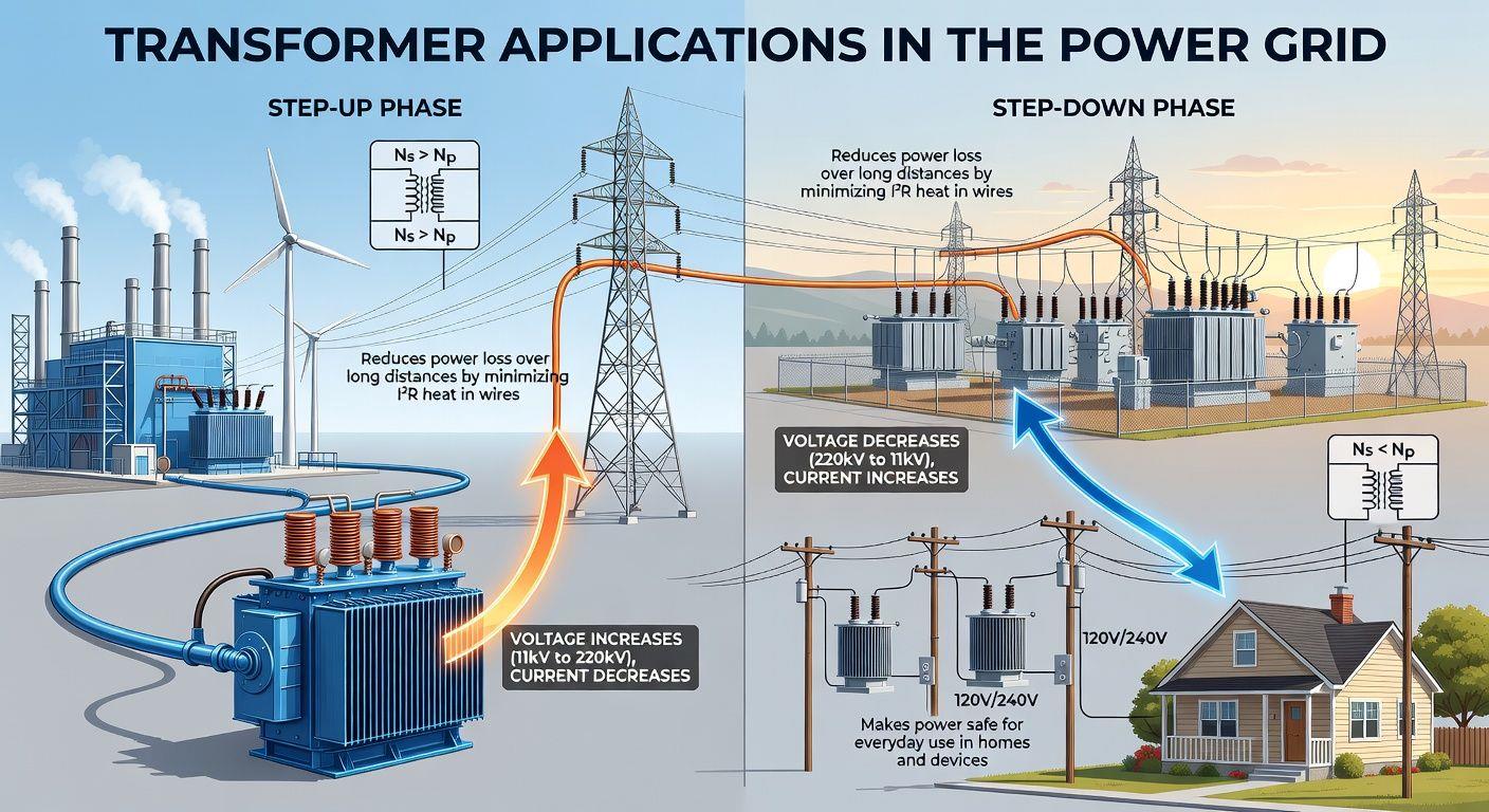
Step-up transformers are built for moving power efficiently over long distances. Step-down transformers are built for delivering that power safely to homes, businesses, and devices.
The basic idea is simple, but choosing the right transformer still takes care. You need to match it to your voltage level, power needs, and specific design requirements.

Legal Disclaimer:
MENAFN provides the
information “as is” without warranty of any kind. We do not accept
any responsibility or liability for the accuracy, content, images,
videos, licenses, completeness, legality, or reliability of the information
contained in this article. If you have any complaints or copyright
issues related to this article, kindly contact the provider above.
Most popular stories
Market Research


Comments
No comment