

OSFP Modules Guide: 400G, 800G And 1.6T Optical Transceivers


Supporting the massive optical bandwidth demands of parallel GPU training, these modules serve as the critical optical connectivity engines for next-generation computing infrastructure, propelling intelligent computing to new heights.
What is an OSFP Module?OSFP stands for Octal Small Form Factor Pluggable. It is an eight-lane high-speed pluggable form factor designed to scale across 400G, 800G, and 1.6T-class applications.
OSFP MSA Revision 5.1 defines implementations supporting 50G-, 100G-, and 200G-class signaling per electrical lane. While the OSFP form factor already supports 1.6T-class modules, standards-based 1.6TbE interfaces and PMDs continue to mature under IEEE P802.3dj, so interoperability depends on the host platform, module implementation, and applicable specification.
Unlike form factors that evolved incrementally from earlier generations, OSFP was purpose-built for the 400G era and beyond. Each of its eight electrical lanes operates at 50 Gbps (PAM4) for 400G modules, 100 Gbps (PAM4) for 800G modules, and is architected to support 200 Gbps per lane for upcoming 1.6T OSFP modules.
A single 1U front panel accommodates up to 36 OSFP ports, delivering aggregate throughput of 28.8 Tbps at 800G per port in a single rack unit. This density, combined with the form factor's superior thermal headroom, is what makes OSFP the preferred choice for AI and hyperscale deployments.
OSFP Electrical Architecture and PAM4 ModulationHigh-speed OSFP host interfaces typically use PAM4 signaling on the electrical lanes. In conventional retimed modules, CDR, equalization, and DSP functions condition the electrical signals before optical transmission. PAM4 encodes two bits per symbol instead of one, effectively doubling the data rate per lane without doubling the physical signaling frequency.
At 800G, each of the eight lanes carries 106.25 Gbps electrical signaling, which the module's internal DSP (Digital Signal Processor) converts to and from the optical domain.
However, the exact signal-processing architecture varies by module type. Linear Pluggable Optics (LPO), for example, removes much of the module-side retiming and DSP functionality to reduce power and latency, while coherent OSFP modules use advanced coherent modulation on the optical line side.
The OSFP mechanical and electrical form factor is defined by the OSFP MSA, while the underlying Ethernet electrical interfaces depend on the signaling generation.
IEEE 802.3ck addresses 100G-per-lane electrical interfaces used by 800G-class systems, while 200G-per-lane interfaces for next-generation 800G and 1.6T Ethernet are being standardized under IEEE P802.3dj. Module management typically uses OIF CMIS; the current published revision is CMIS 5.3.
All OSFP modules support Digital Diagnostics Monitoring (DDM/DOM), giving network operators real-time visibility into module health, receive optical power, transmit bias current, and operating temperature.
OSFP vs QSFP-DD: Key Differences ExplainedThe single most common question engineers ask is whether to chooseOSFP or QSFP-DD. The two form factors serve the same fundamental purpose – 400G and 800G optical connectivity – but they differ in critical ways that directly affect deployment decisions.
The Backward Compatibility Trade-OffOSFP's most significant difference is its lack of backward compatibility with any QSFP form factor. An OSFP module will not physically fit into a QSFP-DD, QSFP28, or QSFP56 cage – the mechanical dimensions are different. While passive OSFP-to-QSFP adapters exist, they add cost, introduce an additional connection point, and are not practical for large-scale deployment.
QSFP-DD, in contrast, accepts QSFP28 and QSFP+ modules natively. For organizations with significant existing investments in 100G QSFP28 optics, this backward compatibility can be worth hundreds of thousands of dollars in reuse value.
Platform Ecosystem: Why OSFP is Winning in AINvidia's decision to adopt OSFP as the native form factor for its Quantum-2 InfiniBand and Spectrum-X Ethernet switch platforms has made OSFP the de facto standard for GPU cluster fabrics. Cisco's 8000 Series and Arista's 7800R3 Series also support OSFP at 800G, though both vendors offer QSFP-DD options in other product lines.
The practical result is that many AI infrastructure teams do not have a genuine choice between form factors – the switch platform they select determines the optics form factor. If you are deploying Nvidia Spectrum-X for a DGX B200 cluster, you are using OSFP modules.
OSFP Module Types by Data RateOSFP modules span three generations: 400G, 800G, and the emerging 1.6T class. Each data rate supports multiple optical variants optimized for different reaches, fiber types, and cost profiles.
400G OSFP Modules400G OSFP modules use 8 × 50G PAM4 electrical lanes and are the current workhorse for enterprise and cloud data center deployments.
SR8 is the most cost-effective option for intra-rack and adjacent-rack connections. It uses VCSEL-based 850nm multimode optics and MPO-16 connectors. DR4 is the most common choice for spine-to-leaf links at up to 500 meters, using parallel single-mode fiber.
For campus-scale connectivity up to 2 km, FR4 uses CWDM wavelength multiplexing over a single duplex LC pair, eliminating the need for expensive MPO trunk cabling.
800G OSFP Modules800G OSFP modules are the current cutting edge, driven primarily by AI training infrastructure and hyperscale data center upgrades. They use 8 × 100G PAM4 electrical lanes.
The 2x400G FR4 and 2x400G LR4 variants deserve particular attention. These modules operate as two independent 400G optical engines inside a single OSFP shell, using dual duplex LC connectors.
A single 800G OSFP 2xFR4 port can connect to two separate 400G FR4 ports on leaf switches using a standard LC breakout cable. This flexibility reduces the number of spine switch ports needed while maintaining full bisectional bandwidth.
800G coherent ZR/ZR+ OSFP modules support distances up to 500 km using tunable C-band DWDM wavelengths and advanced modulation formats such as DP-16QAM.
These modules replace dedicated transponder shelves for data center interconnect, collapsing what was previously a separate optical layer into a pluggable module.
The 1.6T OSFP and OSFP-XD RoadmapThe OSFP form factor is actively evolving to support 1.6 Tbps using 8 × 200G PAM4 electrical lanes. Engineering samples are already in customer validation, with volume production expected in late 2026 through 2027.
The OSFP ecosystem is now extending into 1.6T-class networking. OSFP MSA Revision 5.1 defines OSFP1600 implementations based on eight 200G-class electrical lanes.
At the switch-silicon level, next-generation 102.4 Tbps platforms such as Broadcom Tomahawk 6 and Cisco Silicon One G300 are designed around 200G-class SerDes and 1.6T ports.
At the same time, IEEE P802.3dj continues to finalize standards-based 200G-per-lane and 1.6TbE interfaces, so the 1.6T ecosystem should still be described as an emerging commercial and standards environment rather than a fully mature replacement for 800G.
OSFP Thermal Design: Finned-Top vs Flat-TopOne of the least understood but most operationally critical aspects of OSFP modules is the distinction between thermal variants. Selecting the wrong one can physically damage hardware.
OSFP thermal implementations generally fall into two host-dependent categories. Finned-top, or integrated-heat-sink (IHS), modules include cooling fins as part of the module and are common in switch platforms designed around direct chassis airflow. Flat-top, or riding-heat-sink (RHS), modules expose a flat thermal surface and rely on a host-provided heat sink or cold plate.
Nvidia, for example, uses finned-top twin-port OSFP optics in several Quantum-2 and Spectrum-4 switch configurations, while certain ConnectX-7 and ConnectX-8 implementations use RHS-style OSFP interfaces. Always match the module thermal variant to the exact host platform and cage design.
Finned-Top OSFP (Integrated Heat Sink)Finned-top modules have aluminum cooling fins built into the upper shell. They stand approximately 13–21 mm in height and rely on chassis airflow for cooling. The integrated heat sink enables these modules to dissipate 20 to over 30 watts, making them suitable for high-power 800G LR8 and coherent ZR variants.
Finned-top OSFP modules are used in air-cooled switches including Nvidia Quantum-2, Spectrum-4, Cisco 8000, Arista 7800R3, and Juniper PTX series platforms. The switch chassis provides front-to-back or back-to-front airflow that moves across the fins.
Flat-Top OSFP (Riding Heat Sink)Flat-top modules have a smooth metal top surface, typically 9.5 mm in height. They do not contain integrated cooling fins. Instead, they rely on the host platform to provide thermal management through a spring-loaded riding heat sink built into the cage or, in liquid-cooled environments, a cold plate that makes direct contact with the module surface.
Flat-top OSFP is the standard for NICs and DPUs including Nvidia ConnectX-7, ConnectX-8, and BlueField-3 adapters. It is also preferred in liquid-cooled AI clusters where direct-to-chip cooling eliminates the need for air-cooled heat sinks.
Critical Warning: Thermal Variant MismatchInserting a finned-top OSFP module into a flat-top (RHS) cage can cause physical damage to both the module and the host connector. The extra height of the fins prevents proper seating, and the insertion force required to overcome the mechanical interference can bend electrical pins.
Conversely, installing a flat-top module in a finned-top cage leaves the module without adequate thermal contact, leading to overheating and potential link failure.
Always verify the host device documentation for the required thermal variant before ordering OSFP modules. If you are unsure which variant your platform requires, consult the switch or NIC vendor's transceiver compatibility matrix.
OSFP Power Consumption and Thermal PlanningPower consumption varies significantly across OSFP module types, and at scale, optical power becomes a first-class design consideration.
In a fully populated 32-port 800G OSFP switch, optical power alone can draw 480 to 600 watts – before accounting for the switch ASIC, CPU, fans, and power supply losses.
Total system power for an 800G OSFP spine switch routinely exceeds 1,000 watts. For a data center deploying dozens of such switches, the cooling and power distribution implications are substantial.
On a watts-per-gigabit basis, however, 800G OSFP improves transport efficiency by approximately 35-40 percent compared to equivalent 400G deployments.
Moving from 400G DR4 to 800G DR8 doubles bandwidth while increasing per-port power by roughly 60 to 70 percent – a net efficiency gain that compounds at hyperscale.
Low Power Mode and Operational StatesOSFP supports a hardware-controlled Low Power Mode to manage hot-plug and system power sequencing. Under OSFP MSA Revision 5.1, a module in Low Power Mode must remain within the defined low-power limit of 2 W and disable its transmitters.
The host can transition the module into its advertised operational power class after reset and low-power controls are released. This mechanism helps hosts manage power sequencing and prevents a newly inserted high-power module from immediately drawing its full operating power.
OSFP Connectivity and Breakout ConfigurationsOne of the most operationally valuable features of 800G OSFP modules is their breakout flexibility. A single 800G OSFP port can fan out to multiple lower-speed connections, dramatically improving switch port utilization.
An 800G OSFP host port may support channelization into lower-speed logical interfaces, but the available breakout modes depend on both the switch platform and the optical or cable implementation.
Common platform configurations include 2×400G, 4×200G, and 8×100G. For optical links, the module architecture must also provide the required independent optical paths – for example, a 2×400G FR4 module contains two independent 400G optical engines, while a DR8 module maps its parallel optical lanes differently.
Always verify both the host-port breakout matrix and the transceiver application advertised through CMIS before designing the breakout topology.
Connector and Fiber ConsiderationsOSFP modules use several connector types depending on the variant:
-
MPO-16 (APC): Used by SR8 and DR8 variants. The 16-fiber MPO connector is physically wider than the MPO-12 used in QSFP. Ensure your structured cabling plant uses MPO-16 trunks if you plan to deploy OSFP DR8 or SR8 modules.
Dual MPO-12 (APC): Used by 800G SR8 and 2xSR4 variants for breakout flexibility.
Dual Duplex LC: Used by 2xFR4 and 2xLR4 variants. Standard LC connectors – the most familiar interface for network engineers.
CS Connector: Used by select 400G 2FR4 variants for very high density.
For new structured cabling, prioritize modular, high-fiber-count trunk designs that can be adapted with cassettes or breakout assemblies as optical interfaces evolve.
MPO-16 is important for many current parallel 800G and emerging 1.6T applications, but no single connector choice can guarantee compatibility with every future OSFP or OSFP-XD optical PMD.
Fiber planning should therefore be based on the expected optical architecture, lane count, and migration strategy rather than form factor alone.
OSFP Modules in AI and Hyperscale Data CentersAI training infrastructure is the single largest driver of OSFP adoption in 2026. The bandwidth demands of large GPU clusters simply cannot be met with lower-speed optics without exploding switch counts and oversubscription ratios.
GPU Cluster InterconnectsConsider a typical DGX B200 deployment. Each B200 GPU demands 400 Gbps of host-side network connectivity to avoid being network-bound during large-model training. A single DGX B200 system with eight GPUs requires 3.2 Tbps of aggregate uplink bandwidth. At 400G per port, that is eight leaf switch ports consumed per server.
At 1,024 GPU scale, the spine layer must handle aggregate traffic volumes in the hundreds of terabits per second. Moving from 400G to 800G OSFP at the spine layer doubles bisectional bandwidth without adding switch ports, directly reducing the number of spine switches, optical modules, and fiber runs.
Nvidia's Spectrum-X Ethernet and Quantum-2 InfiniBand platforms, both OSFP-native, are the reference architectures for these deployments. The tight coupling between GPU vendor networking and theOSFP form factor has made OSFP the de facto standard for greenfield AI cluster builds.
Hybrid Architecture: 400G Leaf + 800G OSFP SpineMost hyperscale operators are deploying hybrid fabrics: 400G at the leaf (access) layer for server connectivity and 800G OSFP at the spine layer for inter-switch links. This design recognizes that server NIC speeds lag behind switch-to-switch speeds and that the spine layer is where congestion forms first.
When designed with the appropriate oversubscription ratio – typically 1:1 or 2:1 at the spine layer for AI workloads – this architecture provides a balanced, cost-effective path that extends to 2028 and beyond.
Liquid Cooling and OSFPIn direct-to-chip liquid-cooled AI clusters, flat-top OSFP modules interface with cold plates integrated into the server or switch chassis. The elimination of air-cooled heat sinks reduces thermal resistance and allows higher-power modules – including coherent ZR+ variants – to operate in environments where fan power would otherwise be prohibitive.
For network engineers accustomed to air-cooled optics, the transition to liquid-cooled OSFP modules requires close coordination with the facility and mechanical engineering teams.
The thermal interface material (TIM) between the flat-top module and cold plate must be specified correctly, and cold plate mounting pressure must be verified to ensure reliable thermal contact without damaging the module.
OEM vs Third-Party OSFP Modules: A TCO PerspectiveThe cost differential between OEM-branded and third-party compatible OSFP modules is among the largest in the optical networking industry. Understanding the trade-offs is essential for procurement and engineering teams.
Third-party compatible OSFP modules can offer meaningful acquisition-cost savings, especially in large deployments, but pricing varies significantly by reach, optical technology, volume, qualification requirements, and market conditions.
Procurement teams should compare total lifecycle cost rather than module price alone, including platform qualification, failure rates, warranty coverage, replacement logistics, engineering support, and supply continuity.
What to Verify with Third-Party OSFP ModulesThe quality and reliability of third-party OSFP modules have improved substantially over the past three years, but due diligence remains essential:
EEPROM Coding: Verify that the module reports the correct vendor OUI, part number, and compliance codes for your specific switch platform and OS version. Incorrect coding can trigger compatibility warnings or prevent link bring-up. Power Consumption: Confirm the module operates within your switch's per-port power budget. Some third-party modules draw marginally more power than OEM equivalents, and in a densely populated chassis, the aggregate difference matters. Unit Testing: Always qualify one module in your exact switch model, OS version, and configuration before committing to a full BOM. Warranty and RMA: Evaluate the supplier's warranty terms, RMA processing time, and whether advance replacement is available. A $200 saving per module evaporates quickly if a failure requires days of troubleshooting and replacement lead time. Manufacturing Origin and Quality: Look for manufacturers with ISO 9001-certified production lines, published quality testing procedures, and a track record of supplying optical modules to enterprise or hyperscale customers.AscentOptics manufactures OSFP modules with rigorous quality control – every module undergoes full parametric testing including optical power, receiver sensitivity, spectrum analysis, and system-level traffic testing before shipment. This manufacturer-direct approach delivers OEM-comparable quality at third-party pricing.
How to Select the Right OSFP ModuleFollow this seven-step framework to ensure you specify the correct OSFP module for your deployment:
Step 1: Identify the Host DeviceYour switch, NIC, or DPU determines everything downstream. Retrieve the vendor's transceiver compatibility matrix and note the supported form factor, thermal variant, and any platform-specific encoding requirements.
Step 2: Determine the Thermal VariantIs your host an air-cooled switch that requires finned-top (IHS) modules, or a NIC/DPU that uses flat-top (RHS) modules? If the platform supports both, confirm which variant your specific cage or slot is configured for. This is the most common ordering mistake – and the most expensive to correct.
Step 3: Match the Data Rate400G OSFP modules are adequate for most enterprise leaf-spine deployments and 400G server NIC connectivity. 800G OSFP modules are the right choice for spine switch interconnects, AI cluster fabrics, and any environment where bandwidth demand is growing faster than port count.
Step 4: Determine the Reach Requirement Step 5: Verify Platform CompatibilityConfirm that the module is coded correctly for your switch vendor, model, and minimum OS version. For multi-vendor environments, look for modules that have been qualified across all platforms in your network rather than sourcing separate SKUs for each switch brand.
Step 6: Calculate the Power and Thermal BudgetAdd up the per-port power consumption for all OSFP modules in the chassis. Ensure total optical power plus switch ASIC and system power stays within the chassis power supply rating and that your cooling infrastructure can handle the heat load. A single fully populated 800G OSFP switch draws over 1,000 watts of total system power.
Step 7: Evaluate OEM vs Third-Party OptionsBalance upfront cost savings against warranty coverage, support quality, and qualification confidence. For production AI clusters where every hour of downtime has six-figure consequences, the decision criteria may differ from those for a development or staging environment.
ConclusionOSFP modules have become the backbone of next-generation data center networking. Their eight-lane electrical architecture, superior thermal headroom, and clear roadmap from 400G through 800G to 1.6T make them the form factor of choice for AI training fabrics, hyperscale spine layers, and any deployment where power and bandwidth matter at scale.
The key takeaways are straightforward:
-
OSFP is purpose-built for 400G and beyond, with the thermal capacity to handle high-power coherent optics that QSFP-DD struggles with.
The platform you choose largely determines your form factor. Nvidia Quantum-2 and Spectrum-X environments are OSFP-native.
Thermal variant selection – finned-top for air-cooled switches, flat-top for NICs and liquid cooling – is the most common deployment mistake. Verify before ordering.
Breakout flexibility from 800G OSFP ports delivers 35 to 45 percent cost savings per 100G of delivered bandwidth.
Third-party compatible OSFP modules from qualified manufacturers offer substantial TCO savings without sacrificing reliability, provided you perform proper qualification.
The optical networking industry is in the middle of a generational transition driven by AI infrastructure buildout. The engineers and architects who understand OSFP today are the ones who will build the networks that train tomorrow's models.
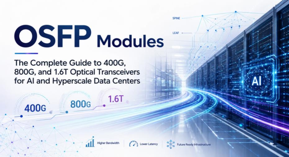
Main image: Figure 1. OSFP Modules for 400G, 800G & 1.6T Networks

Legal Disclaimer:
MENAFN provides the
information “as is” without warranty of any kind. We do not accept any
responsibility or liability for the accuracy, content, images, videos,
licenses, completeness, legality, or reliability of the information
contained in this article. If you have any complaints or copyright issues
related to this article, kindly contact the provider above.
Comments
No comment